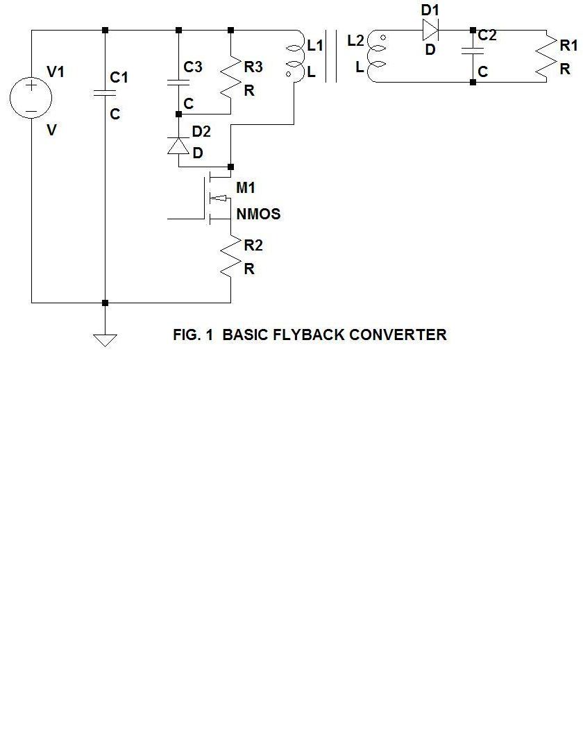
Fig. 1 shows the topology of a basic flyback converter (less the drive control and feedback circuits for simplicity.) This will be the basis for further discussion of key components and the basic function of the converter.
V1 is the source of voltage to be converted. If the source is an AC source it will have to be full wave rectified to DC before it is applied as the DC source to the converter. The full wave rectification circuit is not shown here for simplicity. C1 is the basic input filter capacitor. It must have a large enough value to filter noise from the switching of the transistor M1 and also be high enough to "hold up" the DC voltage to the converter in the event of a line droop. The time to hold-up the system is usually 1/2 AC cycles to 1 full AC cycle.
M1 is the main switching transistor that allows control of the duty cycle of the converter through the action of its control circuit (not shown.) R2 is used to sense peak current through the transistor and the current in the primary, L1, of the transformer consisting of L1 and L2.
R3, C3, and D2 work together to "snub" the peak voltage on the transistor M1 to help control the initial turn-off voltage spike which occurs on the drain of the transistor on each on-off cycle. R3 and C3 are carefully chosen to get the best snubbing without excessive dissipation in R3 or loss of energy being transferred to the secondary circuit.
L1 is the primary of the transformer and must be carefully designed to handle the sometimes high voltage input and the large peak currents that can be required. My previous post covers some of the design considerations for the primary.
The secondary circuit consisting of L2 of the transformer, D1, C2, and R1 should be isolated from the primary side of the circuit to protect uses from electrical shock from the voltage source which might be a high voltage. R1 represents the load which could be a combination of inductance, capacitance, and resistance. An Example would be an electric motor. One important note about C2 is that in flyback circuits, this capacitor has a very high ripple current with high peak values and it must be carefully selected for its current rating and long life. A good choice for this capacitor is the solid aluminum electrolytic capacitor or other long life types for low voltage outputs. Later posts will go into more detail on design of the secondary circuit.

No comments:
Post a Comment